
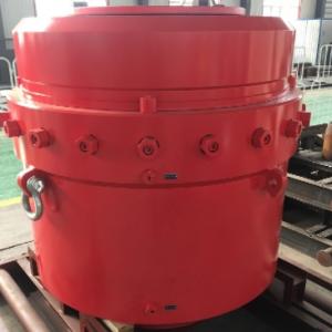
13 5/8-15000PSI Ram BOP
- Product Item : 188
- Category: Cameron U type Ram BOP
- 13 5/8-15000PSI Ram BOP
- 13 5/8-10000PSI annular BOP
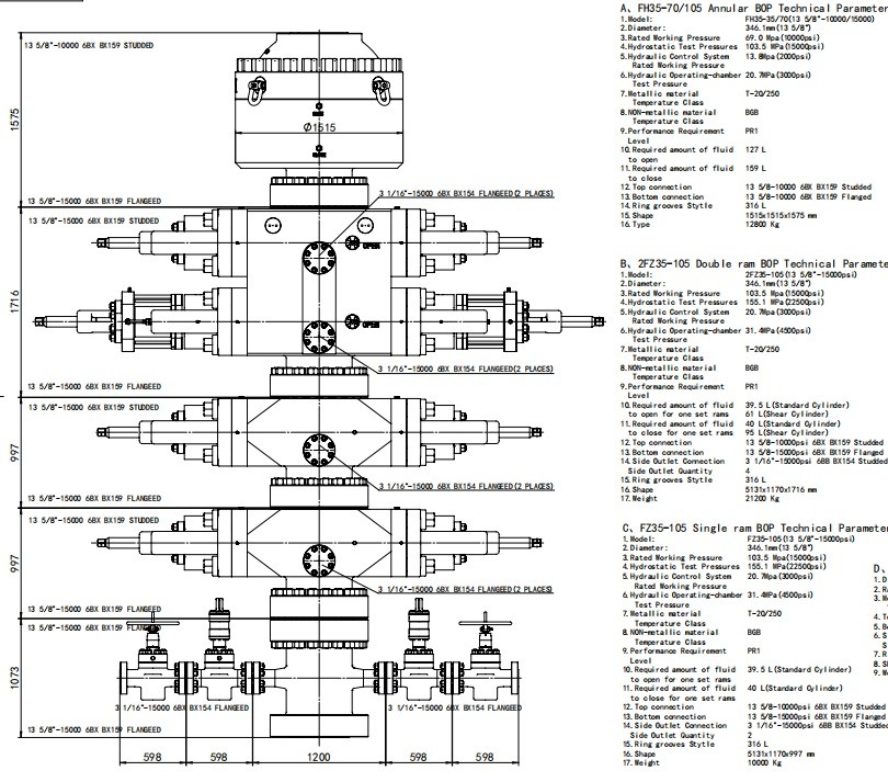
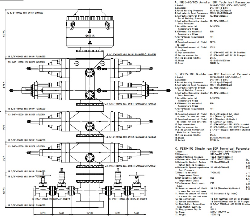
- Single ram BOP Technical Parameters
- double ram BOP Technical Parameters
13 5/8-15000PSI Ram BOP and Annular BOP
The ram blowout preventer is one of the key elements of the well control system. It is mainly used to control the well head pressure during such operations as drilling, servicing and oil testing to prevent any blow out hazard effectively and ensure safe operations. Specifically, it can be used for the following operations:
² When there is a pipe string a well, the circular space between the casing and the drill pipe could
be sealed with matched pipe rams.
² When there isn’t a pipe string in a well, the wellhead could be shut off completely with blind rams.
² After the well has been sealed, such special operations as mud circulation, choking, killing and
well washing can be performed through choke and kill manifold connected to spool and side outlet of BOP.
² When used together with the pipe manifold for choking and killing, it can control the well pressure
effectively and achieve near-balance well killing operations.
Type: FZ-Single Ram Blowout Preventer
2FZ-Double Ram Blowout Preventer
3FZ-Triple Ram Blowout Preventer
Please see the following table for the bore codes:
Nominal Working Pressure: There are six kinds of working pressures as listed in the following table.
Table 2 Nominal Working Pressure Rating
|
14MPa(2,000psi), |
21MPa(3,000psi) |
35MPa (5,000psi) |
|
70MPa (10,000psi) |
105MPa(15,000psi) |
140 MPa(20,000psi) |
2. Temperature Grades of Metal Materials:
Table 3 Temperature Grades of Metal Materials
|
Temperature Grade Code |
API Code |
Working Temperature Range |
|
T75 |
75 |
-59~121℃(-75~250 ºF) |
|
T20 |
20 |
-29~121℃(-20~250 ºF) |
|
T0 |
00 |
-18~121℃(0~250 ºF) |
3. Temperature Grades of Non-metal Sealing Elements in contact with Well Liquids.
Combinations of two letters are used to indicate the upper limits and the lower limits as described below.
Lower Limit (First Letter) Upper Limit (Second Letter)
A 15ºF(-26℃) A 180ºF(82℃)
B 0ºF(-17.8℃) B 200ºF(93℃)
C 10ºF(-12.2℃) C 220ºF(104℃)
D 20ºF(-6.7℃) D 250ºF(121℃)
E 30ºF(-1℃) E 300ºF(149℃)
X 40ºF(4℃) X 180ºF(82℃)
For example, AB represents a temperature grade ranging from -26℃ to 93℃. The specific temperature grade is marked with a code on a sealing member.
2.2 Technical Parameters of the Ram Blowout Preventer
Please see the following table for the technical parameters:
Table 1 Parameters of Ram Blowout Preventer
|
Item |
Single Ram Blowout Preventer |
Double Ram Blowout Preventer |
||
|
Model |
13 5/8” |
13 5/8” |
||
|
Top Connection |
Studded |
Flanged |
Studded |
Flanged |
|
Bottom Connection |
Flanged |
Flanged |
Flanged |
Flanged |
|
Weight Kg |
7888 |
8807 |
14572 |
15491 |
|
Height (H) mm |
1085 |
1430 |
1745 |
2090 |
|
Bore Size |
346.1 mm (13 5/8″) |
|||
|
Shell Test Pressure |
157.5MPa (22,500psi) |
|||
|
Rated Working Pressure |
105 MPa (15,000psi) |
|||
|
Hydraulic Control System Strength Pressure |
31.5 MPa(4,500psi) |
|||
|
Hydraulic Control System Working Pressure |
21 MPa(3,000psi) |
|||
|
Recommended Hydraulic Control Operating Pressure |
8.4~10 .5MPa(1,200~1,500psi) |
|||
|
Opening volume for one set of Ram |
37L |
|||
|
Closing volume for one set of Ram |
40L |
|||
|
Hydraulic Port |
NPT 1” |
|||
|
Side Outlet note |
3 1/16″-15000psi (it’ll change according to different contract) |
|||
|
Temperature Grade note |
T20(-29~121℃) (it’ll change according to different contract) |
|||
|
Closure Ratio |
1: 9.5 |
|||
|
Other Descriptions: The designing and the manufacturing of the blowout preventer are in accordance with the API Spec 16A norms. The resistance to the corrosive stress of hydrogen disulfide of the internal parts of the blowout preventer in contact with the well liquids conforms to the requirements specified in NACE MR-01-75. |
||||
Table 2 Specifications of Available Rams
|
Blind, 2 3/8″,2 7/8″,3 1/2″,4″,4 1/2″,5″,5 1/2″, 6 5/8″, 7″,9 5/8″, Shear |
3. Working Principles
3.1 Principles of opening and closing
When high pressure oil of hydraulic control system comes into the left and right closing chambers of cylinders through oil channel inside body from hydraulic port, the impelling pistons drive ram shafts with ram assemblies to the center of wellhead along ram chamber to close the well. When high pressure oil comes into the left and right opening chambers of cylinders, the impelling pistons drive the ram shafts with ram assemblies away from the center of the wellhead to open the well. The opening and closing is controlled through the reversal valve of the hydraulic control system.
██ Rams closed, bonnets opened
██ Rams opened, bonnets closed
Figure Hydraulic system opening and closing drawing of rams & bonnets
3.2 Principles of well pressure sealing
A ram blowout preventer can only effectively close a well when all the four seals have taken effect. These four seals include the seal between the ram top seal and the body, the seal between the ram front seal and the pipe, the seal between the body and the bonnet, and the seal between the ram shaft and the bonnet.
The ram sealing process is divided into two steps. In the first step the hydraulic oil forces the ram shaft to impel ram packer to deform and seal the front part, and top seal seals top with compressed rubber, so it establishes a primary sealing. In the second step, with the help of the pressure inside the well the rams are impelled from behind to make ram packer deform more and the rams are also impelled from the bottom to let the body adhere tightly to top, thus achieve the reliable sealing. It is called the well pressure assisted sealing effect.
4. Structures and features
4.1 Structural Features
Ø The opening and closing for both rams and bonnets are all actuated hydraulically by one and same hydraulic path. The bonnets’ opening and rams’ closing are actuated by one and same hydraulic path and action; then the bonnets’ closing and rams’ opening are actuated by one and same hydraulic path and action
Ø Ram assembly: ram bodies are in long-round shape. Ram rubber is divided into two parts: front packer and top seal. This structure is easy and convenient for ram rubber to change. The front packer and top seal could be changed respectively according to damage condition in fact.
Between body and bonnets, a floating well-pressure-assistant-sealing structure is used on bonnet. So need less pre-tighten force is needed, and it’s reliable.
16.weight 12800 Kg
17.Weight 21200 Kg
17.Weight 10000 Kg
INQUIRY
CATEGORIES
- Cameron U type Ram BOP
- Shaffer type annular BOP and Ram BOP
- hydril type annular BOP GK
- BOP control system Koomey unit
- MSP diverter and shaffer Diverter
- MWD spare Circulating sleeve Centralizer Current-limiting ring
- 3 inch RR Type spring reset relief valve in mud pump F1600 manufacturer
- WPCE Wireline Pressure Control Equipment
- Pneumatic pipe spinner SSW40
- ESP pump Electric Submersible Pump and Spare Parts
- Top drive system
- wellhead equipment
CONTACT US
Name: Steven
Mobile:+8615369805074
Whatsapp:+8613512492572
Email:sales@fengliangpetroleum.com
Add:Binhai New Area, Tianjin City