

Choke and Kill Manifold
- Product Item : 108
- Category: wellhead equipment
- Choke and Kill Manifold
- Process of Choke and Kill Manifold
- advantages of Choke and Kill Manifold
- vital part of the well control system
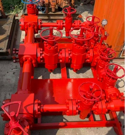
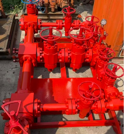
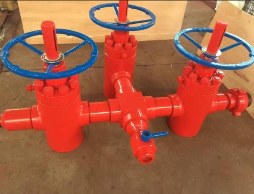
Choke and Kill Manifold
The Choke and Kill Manifold is a vital part of the well control system, designed to manage pressure during drilling operations—especially during kicks or wellbore influx situations.
The Choke and Kill Manifold is a vital part of the well control system, designed to manage pressure during drilling operations—especially during kicks or wellbore influx situations.
Choke – The Basic Principle
A choke introduces a variable restriction in the wellbore fluid path to maintain backpressure on the formation. Adjusting the choke helps control flow rate and bottom-hole pressure, enabling safe kick circulation and avoiding blowouts.
Think of it like controlling a water hose with your thumb to regulate pressure and direction.
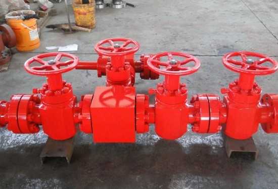
Key Components & Their Functions
- Target Flange
Function: Connects the manifold to external lines like choke and kill lines.
Example: Enables safe fluid transfer during a kill operation through the kill line.
- Gate Valve
Function: Isolates individual flow paths or components within the manifold.
Example: Shut off upstream/downstream flow to replace a choke without disturbing well pressure.
- Adjustable Choke
Function: Manually controlled choke to vary flow resistance and maintain pressure.
Example: Used to gradually circulate formation influx at controlled backpressure during a well control event.
- Hydraulic Choke
Function: Remotely operated adjustable choke—safer for HPHT wells.
Example: Enables choke adjustments from the driller’s console during kicks, minimizing manual risk.
- Studded Cross / Tee / Special Tee
Function: Forms flow junctions and structural layout for manifold routing.
Example: Allows parallel routing to flare line and separator during multipath circulation.
- Spacer Spool
Function: Provides vertical or horizontal spacing and alignment between manifold components.
Example: Aligns components like a choke and valve that differ in elevation or thread pattern.
Why the Choke Manifold Matters
Controls kick pressures
Routes flow to flare or separator
Enables soft shut-in
Provides dual flow paths (redundancy)
Safely bleeds off excess pressure
Quick Insights:
Why 2 chokes?
Backup choke ensures redundancy if one fails.
Choke in BOP system?
To maintain backpressure and circulate out kicks safely.
API 53 Spec – Bleed Line?
Diameter must be at least equal to the choke line for safe bypass.
Best Practices Onsite:
Daily valve checks
Grease moving parts regularly
Fully operate valves to detect sticking
Keep choke
What are advantages of Choke and Kill Manifold ?
01 Improve safety
The choke&kill manifold contains multiple valve types and multiple valves, which can cut off the wellhead in time in an emergency to ensure the safety of the drilling platform.
02 Save costs
The choke&kill manifold is a centrally controlled system that can bring together various valves, sensors, etc. to reduce maintenance costs.
03 Enhance stability
The choke&kill manifold has various automatic control functions, which can adjust the pressure at the wellhead in time to avoid the situation from getting out of control and improve the stability of the drilling platform.
04 Improve production efficiency
The choke&kill manifold can realize online monitoring of wellhead pressure, flow, and other parameters, and automatically adjust according to these parameters, thereby improving production efficiency.
05 Meet environmental protection requirements
The choke&kill manifold can reduce the fluctuation of wellhead pressure and the waste discharged, thereby reducing the impact on the environment.
06 Simple operation
The choke &kill manifold has a simple structure and is easy to operate. Operators only need to perform simple operations to complete important pressure control work.
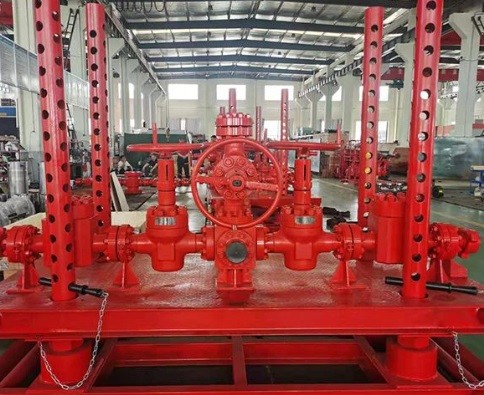
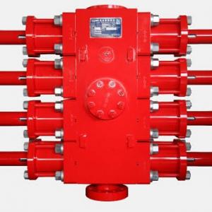
Types of Choke and Kill Manifold
4/5/8 valves choke manifold
The working principle of the 4-valve manifold is to use four valves to control the flow direction and flow rate of the fluid. Two of the valves are called directional control valves, which control the flow direction of the liquid. The other two valves are called flow control valves, which control the flow rate of the liquid.
Stand pipe manifold
It is mainly used to regulate and distribute oil and gas at the wellhead. It can accurately control the flow and pressure of oil and gas to ensure safe and stable production.
Process of Choke and Kill Manifold
Material purchasing
Purchase high-quality raw materials according to contract grade requirements
Rough machining
Carry out preliminary processing according to the rough processing drawing
Heat-treatment
According to the customer's hardness requirements, the corresponding heat treatment process is carried out
Final Machining
Finishing steps according to drawings
Surface treatment
Rust removal, polishing, spraying and other processes are carried out on the processed parts
Inspection
Each component is strictly inspected, including visual inspection, dimension inspection, pressure test, etc., to ensure that each component meets the quality standards.
Assembly
Assemble various components according to design requirements to ensure full compliance with customer requirements
Pressure testing
Hydrostatic pressure test according to grade requirements, must comply with API requirements
Packaging
Use transportation packaging suitable for long-distance and export to prevent product damage during transportation


INQUIRY

CATEGORIES
- Cameron U type Ram BOP
- Shaffer type annular BOP and Ram BOP
- hydril type annular BOP GK
- BOP control system Koomey unit
- MSP diverter and shaffer Diverter
- MWD spare Circulating sleeve Centralizer Current-limiting ring
- 3 inch RR Type spring reset relief valve in mud pump F1600 manufacturer
- WPCE Wireline Pressure Control Equipment
- Pneumatic pipe spinner SSW40
- ESP pump Electric Submersible Pump and Spare Parts
- Top drive system
- wellhead equipment
CONTACT US
Name: Steven
Mobile:+8615369805074
Whatsapp:+8613512492572
Email:sales@fengliangpetroleum.com
Add:Binhai New Area, Tianjin City